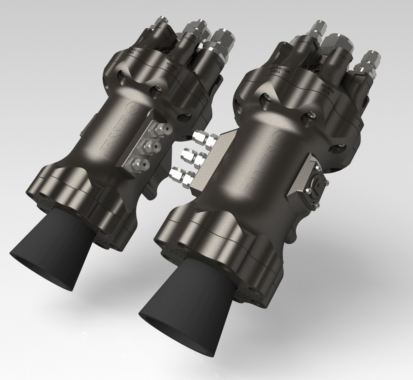
Jessie & James Rocket Engines
A pair of 750 lbf 3D printed pressure-fed liquid rocket engines, that utilize kerosene & gaseous oxygen as propellant.

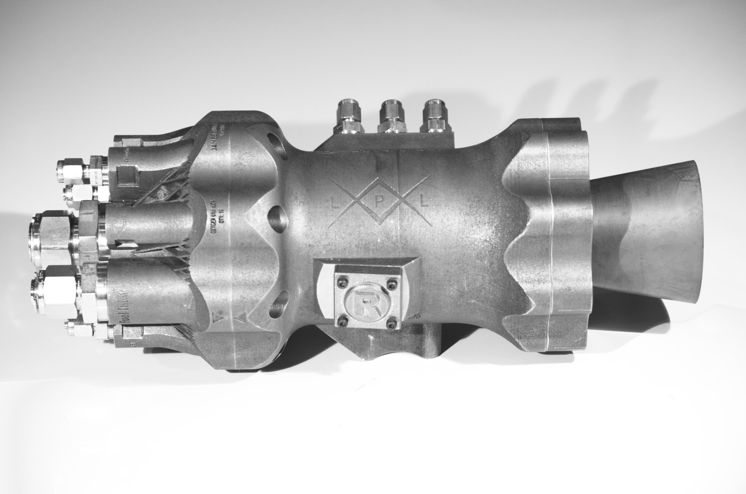
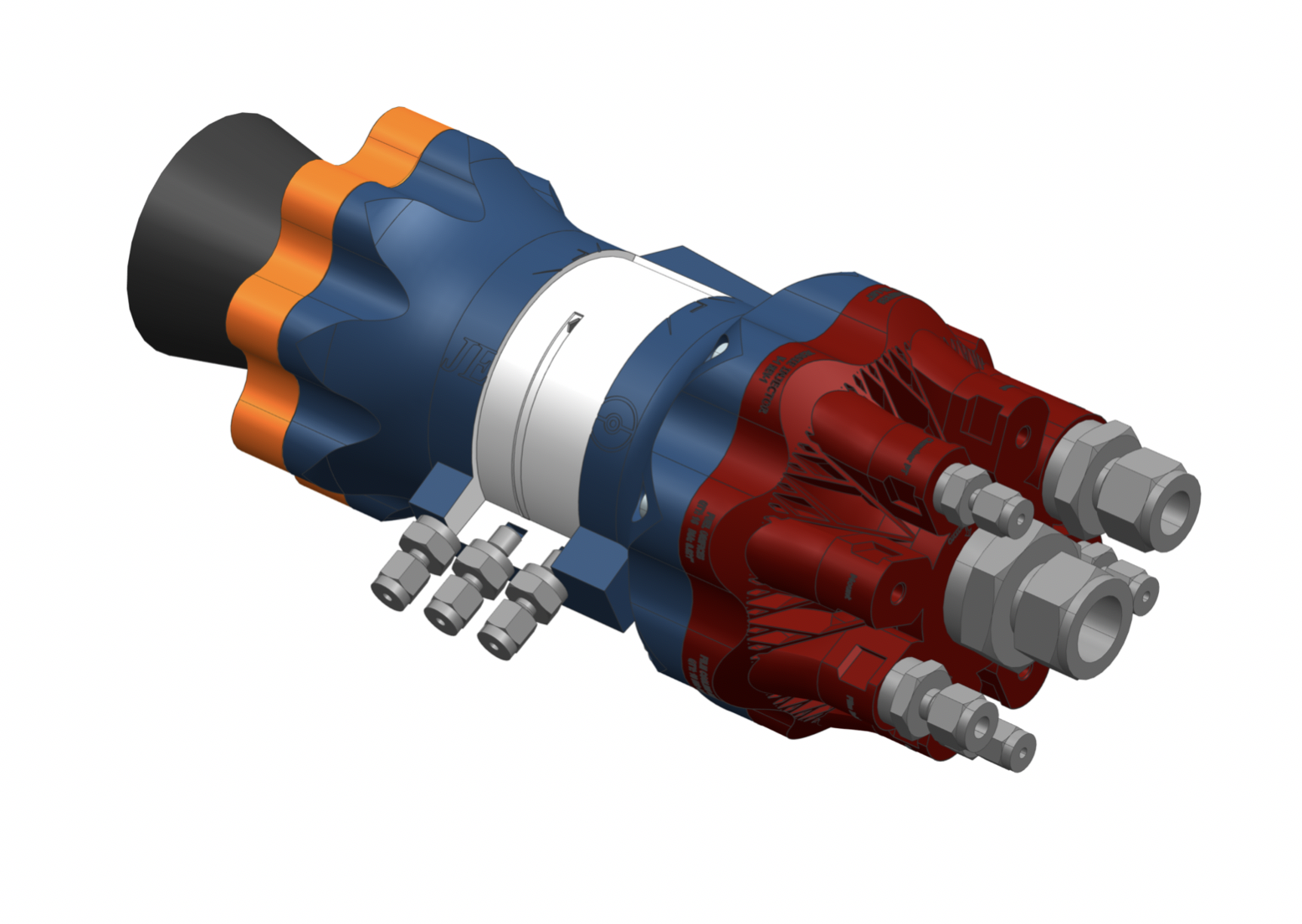
CAD Rendering of the Jessie & James Engines Integrated on Mobile Test Stand

Summary
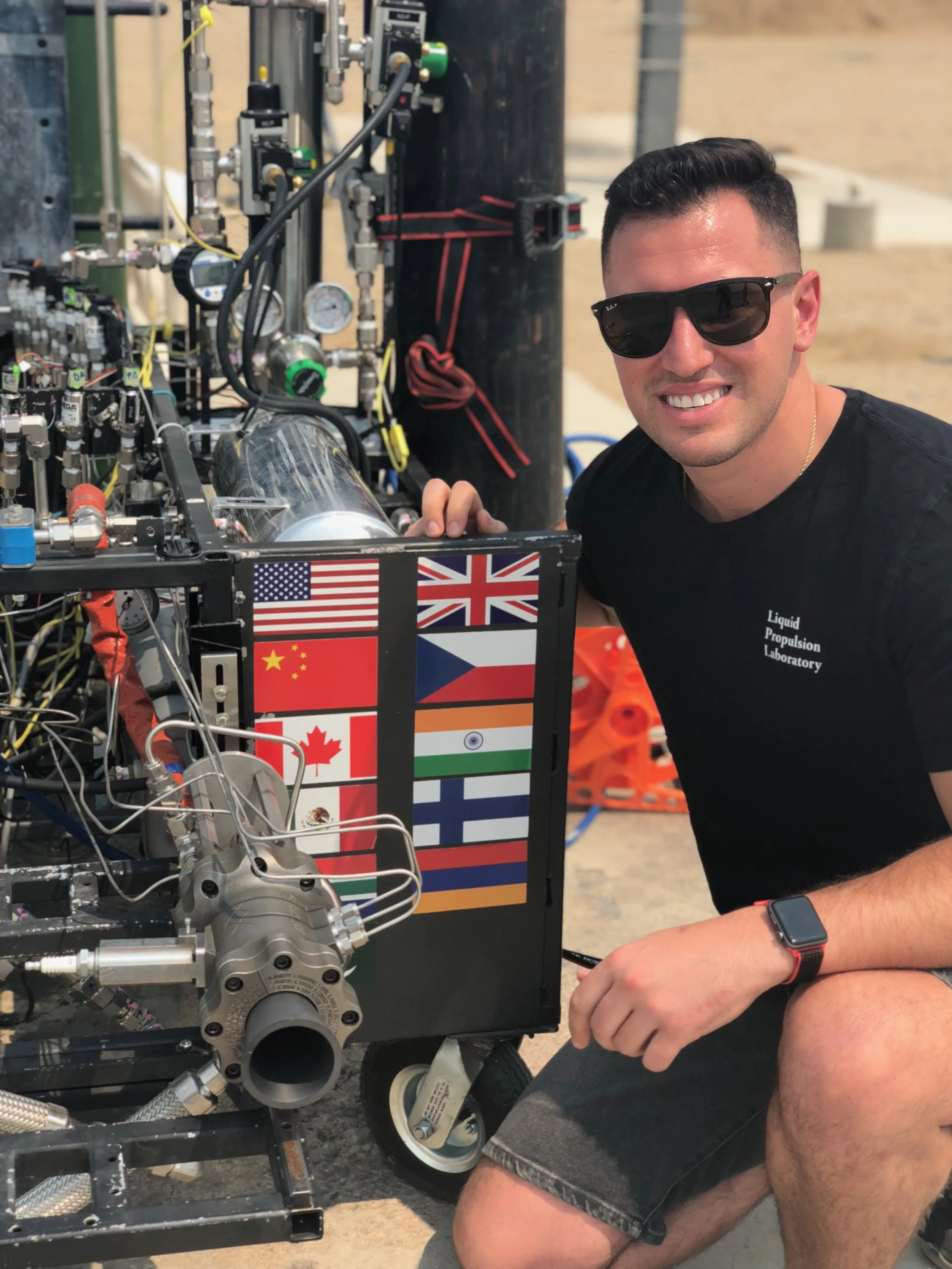
Mike Moruzzi and I conceived & owned the entire Jessie & James project during our final semester of graduate school. The engine(s) went from conception to full fabrication and assembly in 4 months. Today they serve as LPL’s workhorse engines to be developed upon and learnt from for years to come.
Purpose
To introduce the lab to this newly adopted additive manufacturing process, quantify and validate initial beliefs that this process will increase design capabilities, improve iteration turnaround time, decrease development cost, test the resources and manufacturing capabilities of the university, and to provide familiarity to designers and process engineers as the laboratory moves toward more complex rocket engine designs in the near future.
Mike Moruzzi and I saw the lab was lacking knowledge & experience in additive manufacturing & post-processing. As we transferred leadership January 2018, we wanted to take on a technical role by teaching the lab this process by designing and building the universities first 3D printed rocket engine during our final semester of graduate school. The overall design & fabrication process as well as lessons learned could be transferred over to the labs next rocket engine, Balerion, a relatively more complex engine that is currently in development.
Interested in learning about additional reasons for developing Jessie & James
My Personal RESPONSIBILITIES
Trade Studies
System Level Sizing (Design Point, Injector/Nozzle Sizing, Engine Sizing)
Design Tool Creation (Matlab GUI to aid in iteration for design optimization)
Sealing Systems
Fastener Sizing
Procurement
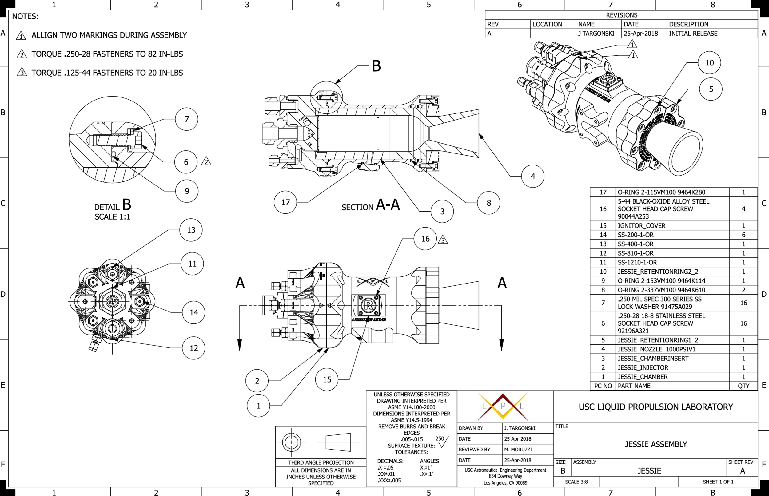
Drawings
Tolerance Stackups
Oversaw 3D Printing Process
Oversaw Machining Process
Engine Assembly
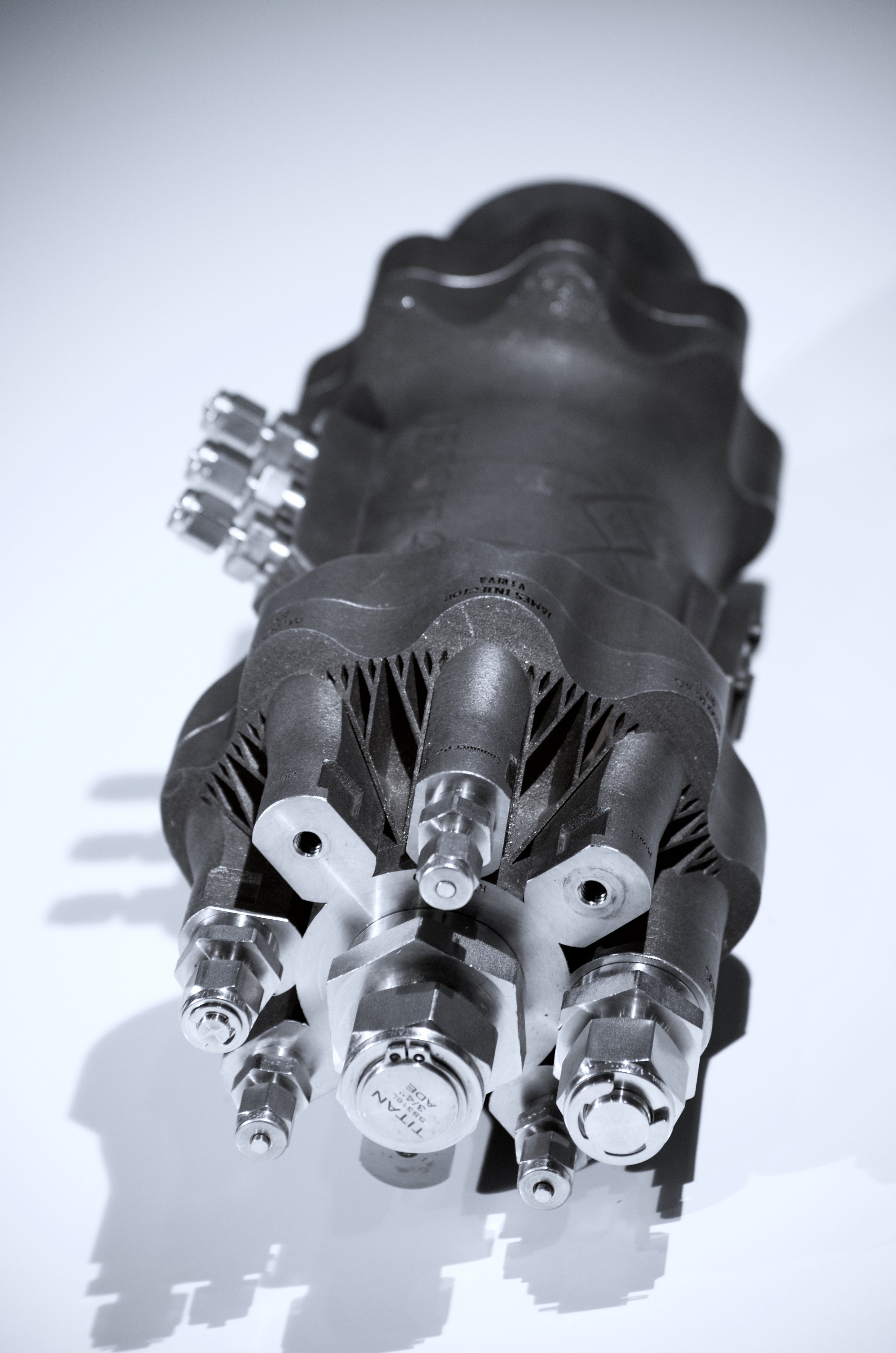
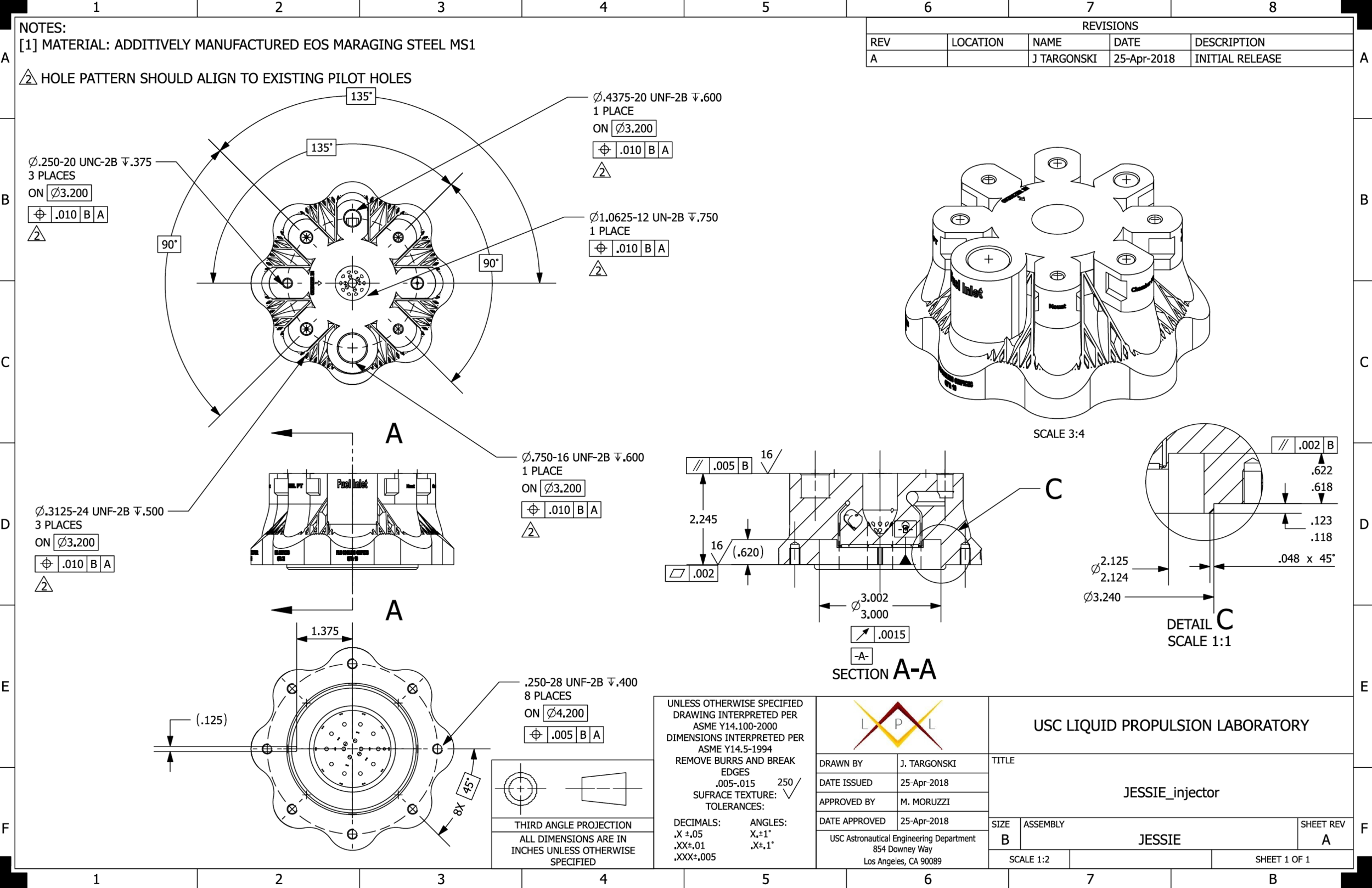
Injector Trade Study
A design requirement was for a single injector to be capable of testing the J&J engines individually or simultaneously, all while maintaining a minimum stiffness of 20%. Since the propellants of J&J are both incompressible (Kerosene) & compressible (Gaseous Oxygen), I conducted a derivation to determine the relationship between mass flow rate & pressure, for a given pressure drop & constant orifice total area. This relationship assisted me in sizing the injectors.
Determining a Design Point
My personal objective was to determine a design point that would optimize the engine(s) performance, thus maximum thrust. One design constraint was the test infrastructure, as the engine(s) needed to be designed to integrate & operate on the lab’s existing test stand (Hydra). Since thrust is the product of mass flow rate & equivalent exhaust velocity, both quantities are to be optimized. The mass flow rate is solely a function of the test stands capabilities as J&J are pressure fed. Neglecting the equivalent exhaust velocity at this stage, this was taken into account later, we were interested in picking a nominal design point that maximized Hydra’s performance. I developed an iterative process and concluded that a total mass flow rate of 1.15 kg/s with an OF ratio of 1.875 was the highest safe operating condition attainable in Hydra’s current configuration.
1-D Engine Sizing & Graphical user interface creation
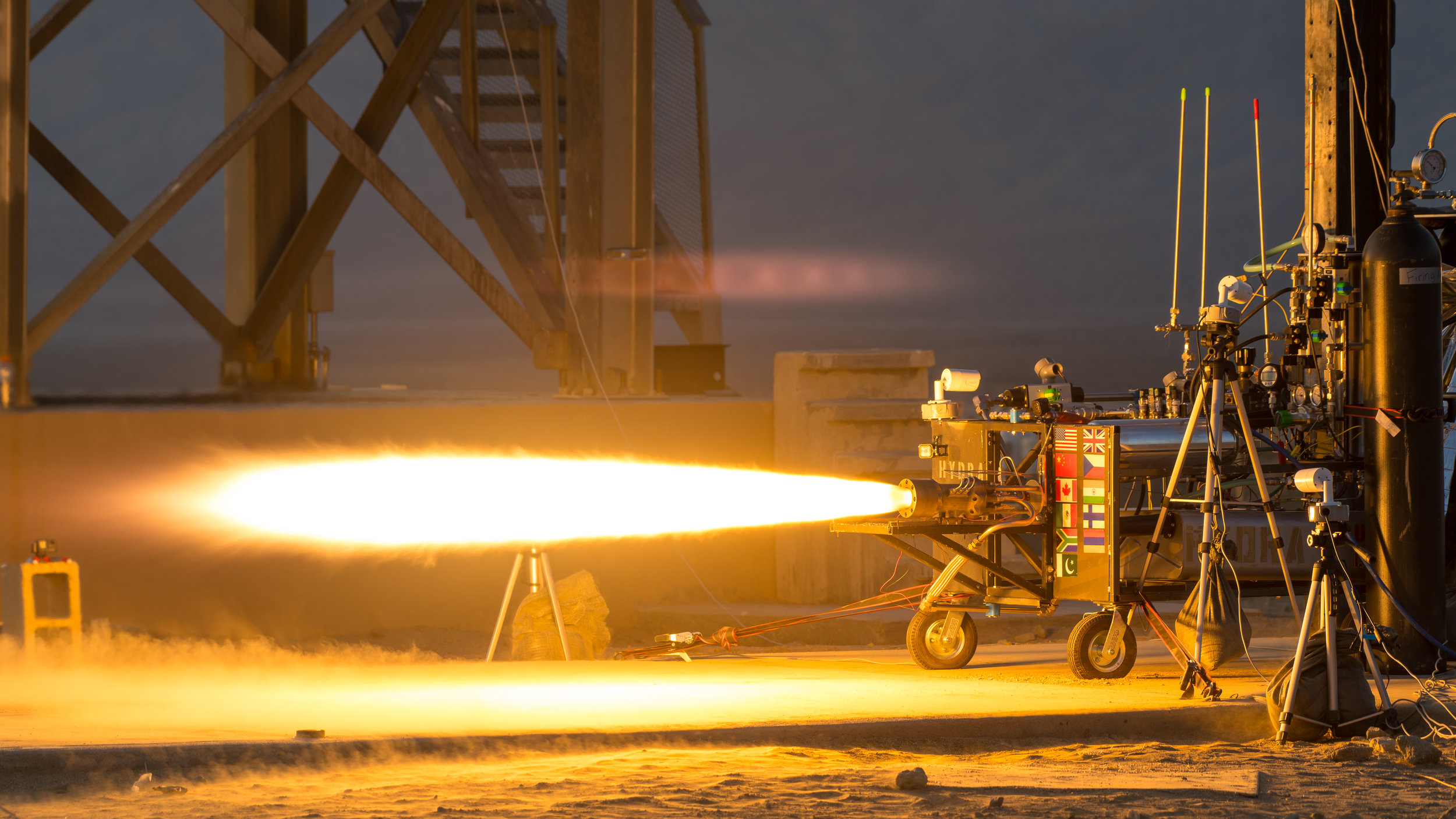
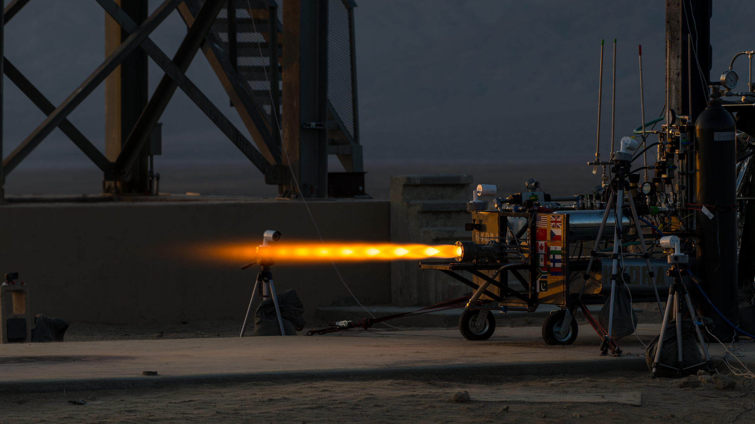
Prior to us generating the engines in 3-D via Siemens NX CAD software, I determined all critical dimensions for the rocket engine to function nominally. This includes but is not limited to throat diameter, area ratios, etc. The sizing geometry constantly changed during the project; whether it was due to printing restrictions, component availability, or just through “in-design iterations”. To increase my efficiency, which freed up time to accomplish different tasks, I created a graphical user interface, GUI, in Matlab to update system level sizes instantly. I took the theory and process of liquid rocket engine sizing and created a presentation which I presented to members of the LPL in April of 2018. At its designed operating conditions a single engine would produce 750 lbf of thrust.
“John Targonski presents first order considerations and governing equations for rocket engine chamber and nozzle sizing. Includes application for the Jessie & James engine and discussion of design tools for the purpose of iteration.”
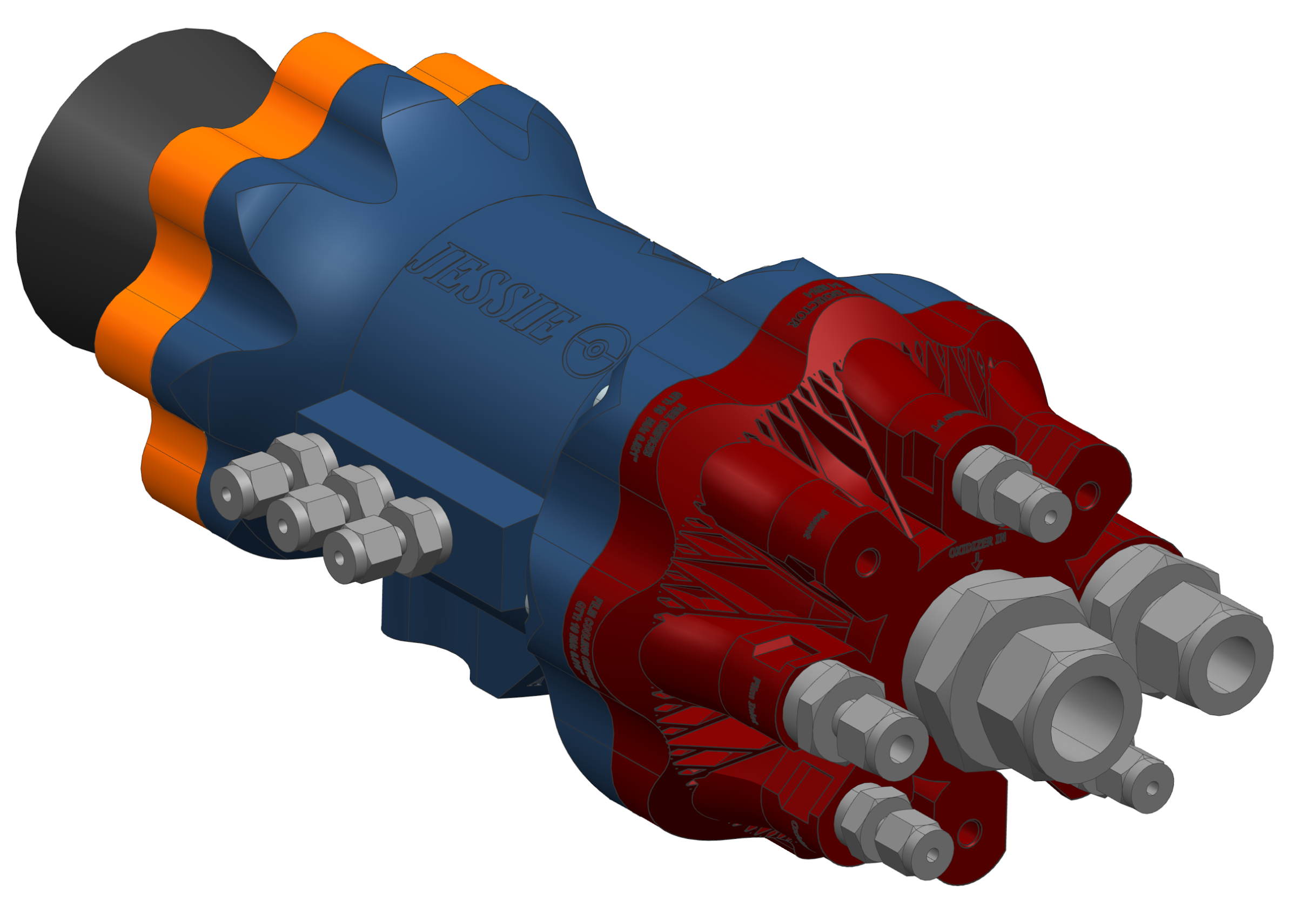
Design
During the design phase, Mike and I set on showcasing the increased capabilities available to designers enabled by additive manufacturing. Simplicity, modularity, manufacturability, assembly, and reusability were all key features we wanted to emphasize. Once I calculated the engine level sizing, Mike & I worked together to brainstorm and implement creativity, elegance, and robustness in the overall design. We presented a Critical Design Review on March 30, 2018 & closed out all action items within 1 week’s time.
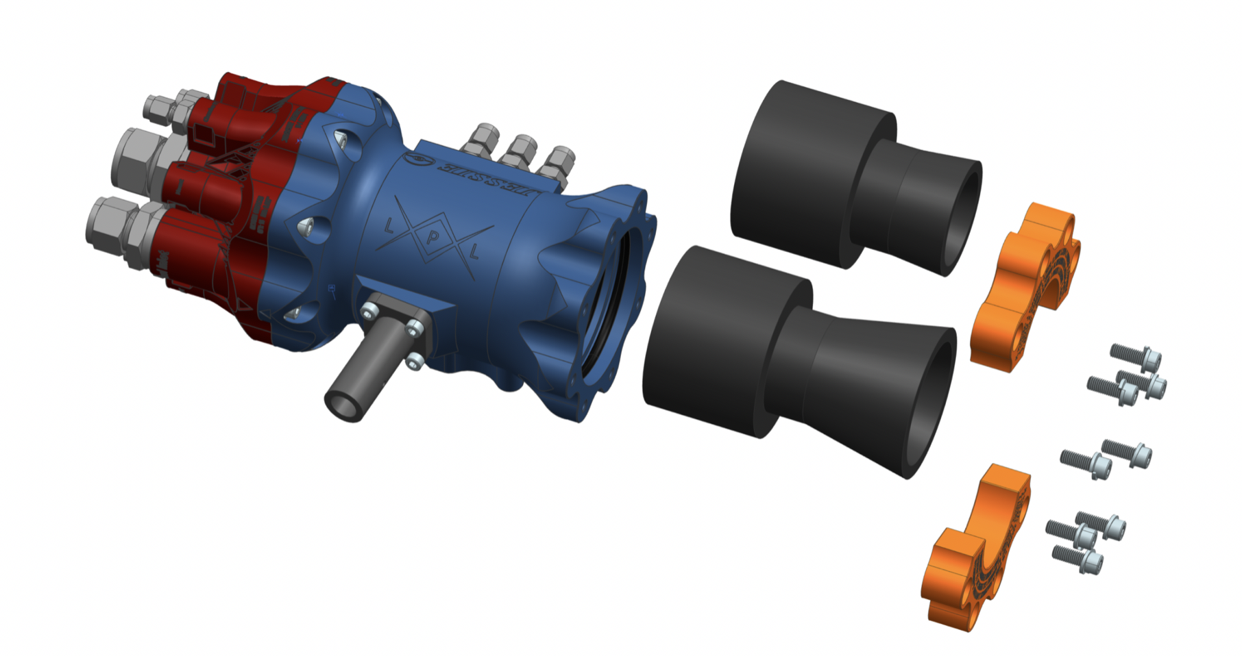
Load Determination, Fastener & Seal Sizing

An example of design, simple analysis, and procurement can be illustrated when I determined the fasteners and seals that would be featured on the J&J engines. I used “back of the envelope” calculations to determine engine loads and predict that the selected fasteners can withstand those loads.
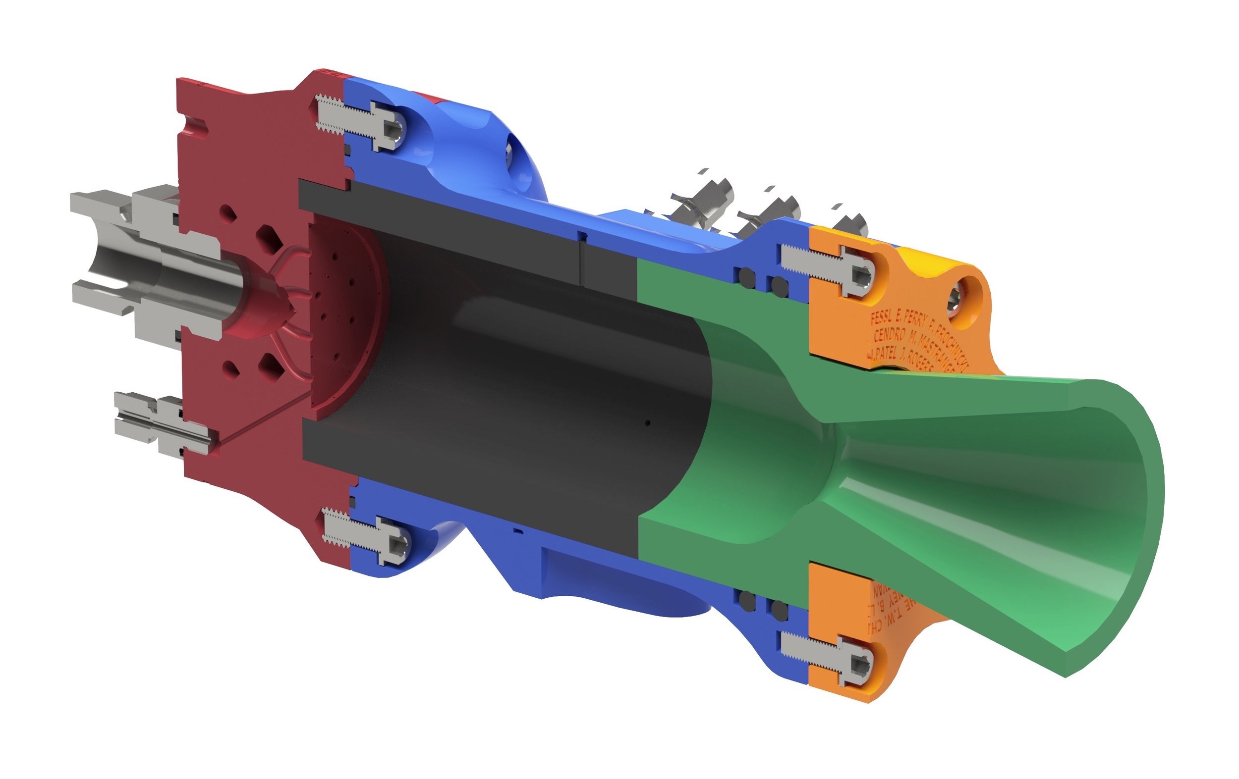
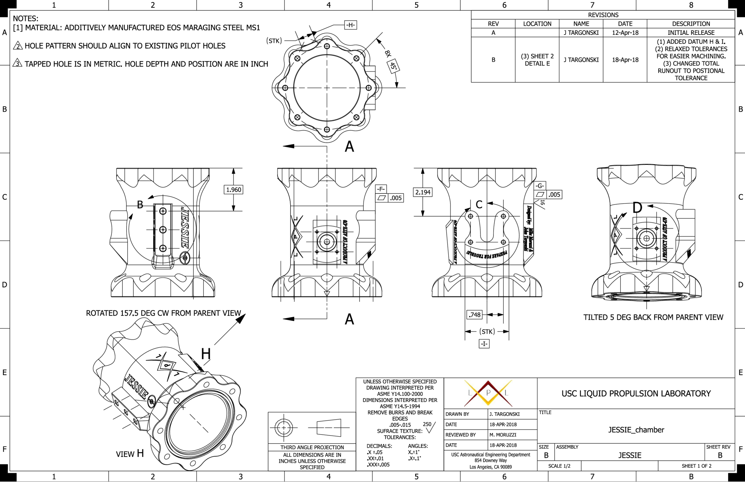
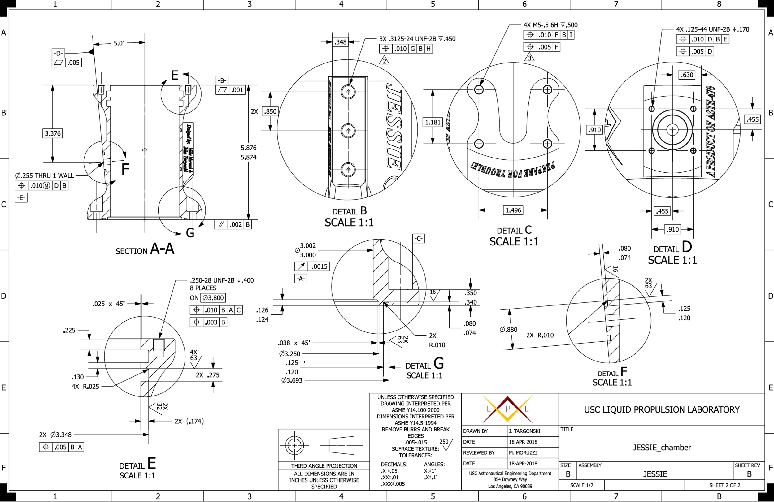
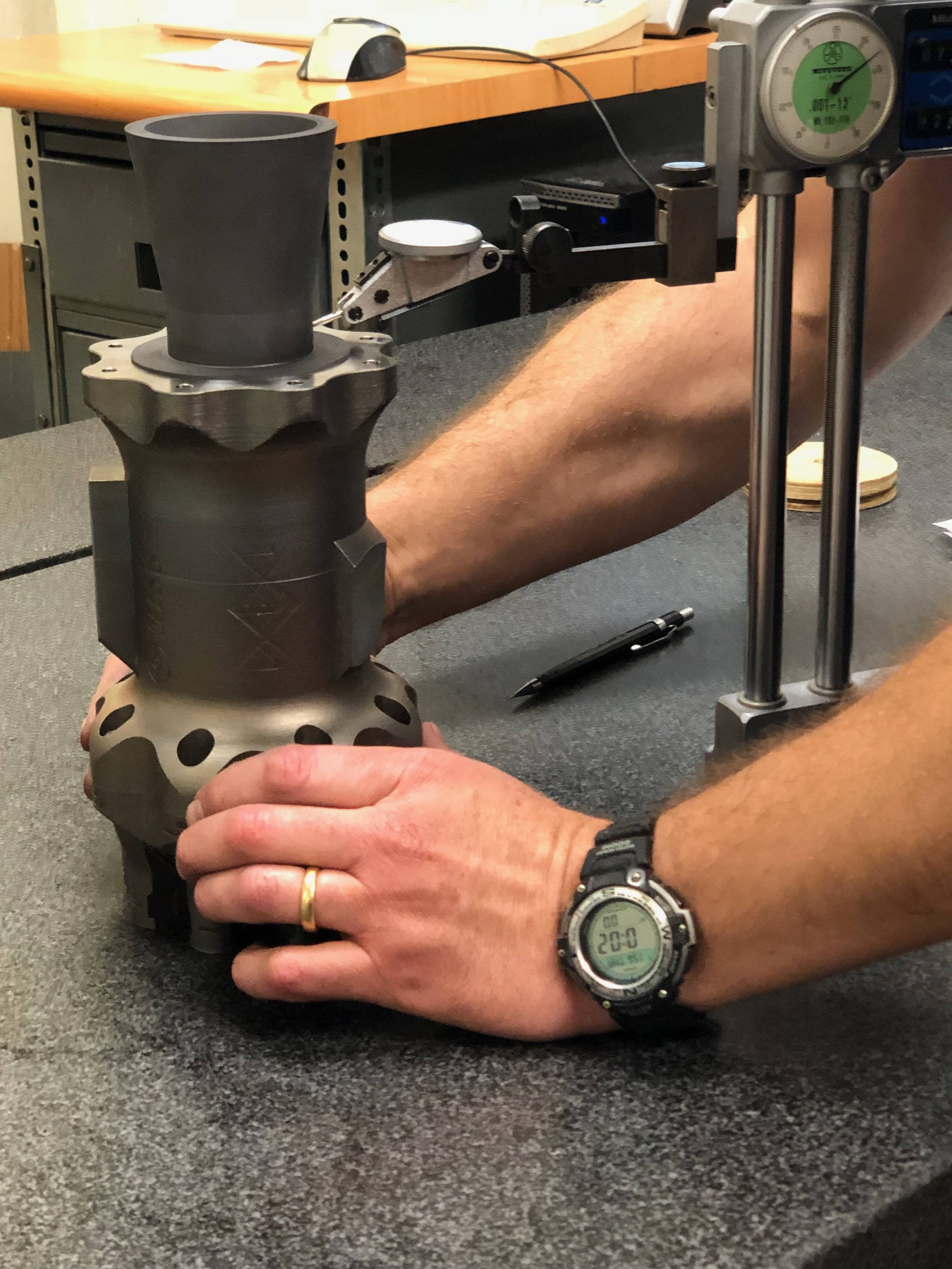
GD&T & Tolerance Analysis
Axial Stack-Up of critical dimensions with their respected tolerances to ensure the thermal control, ablative graphite, is compressed (within structural limits) or exposing the chamber by no more than the length of a human hair (0.003”).
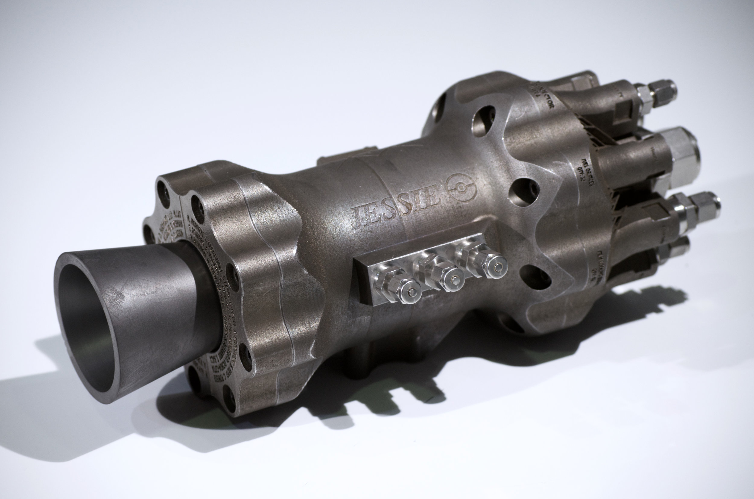
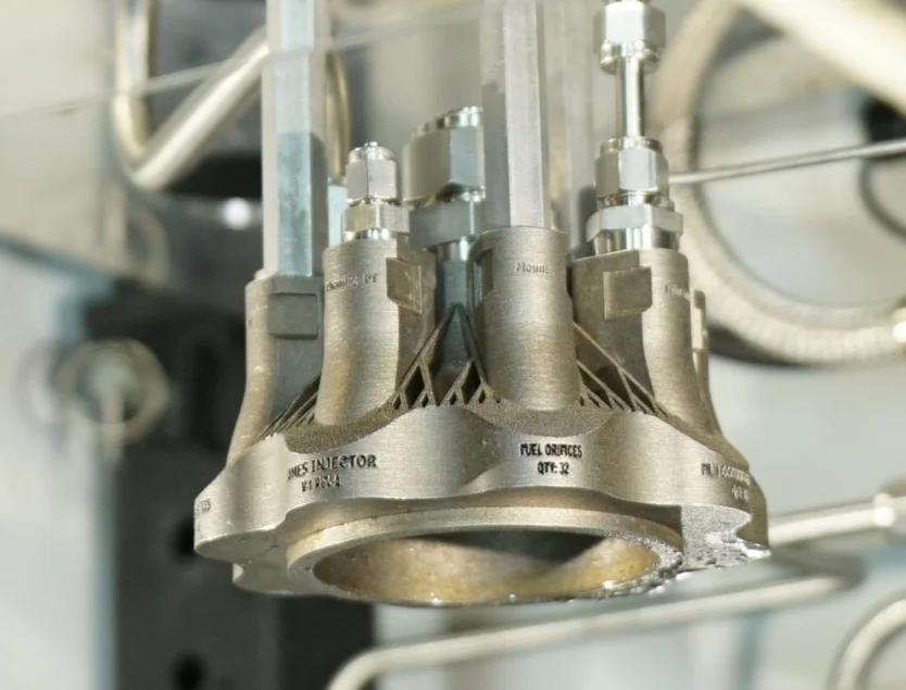
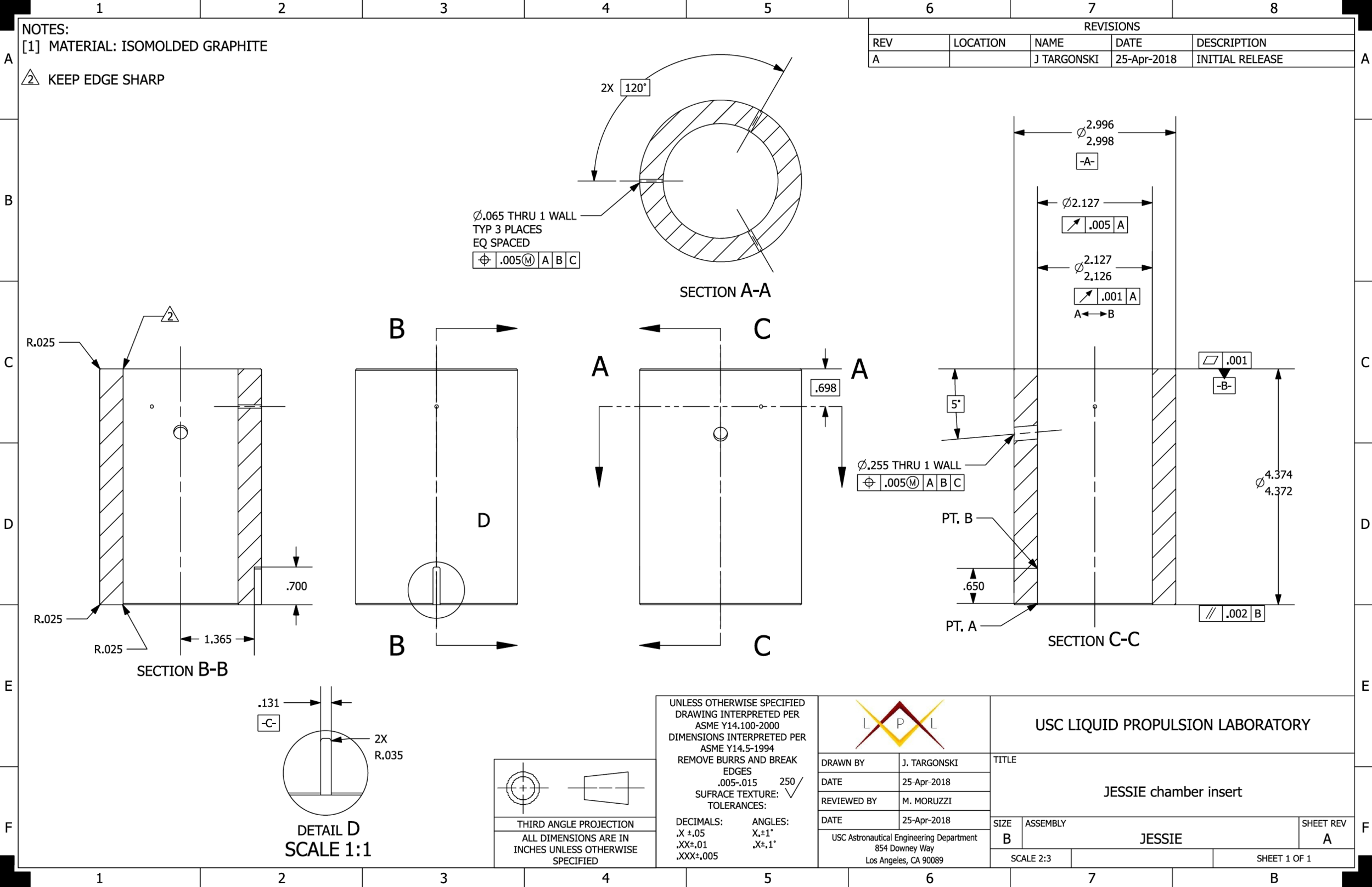
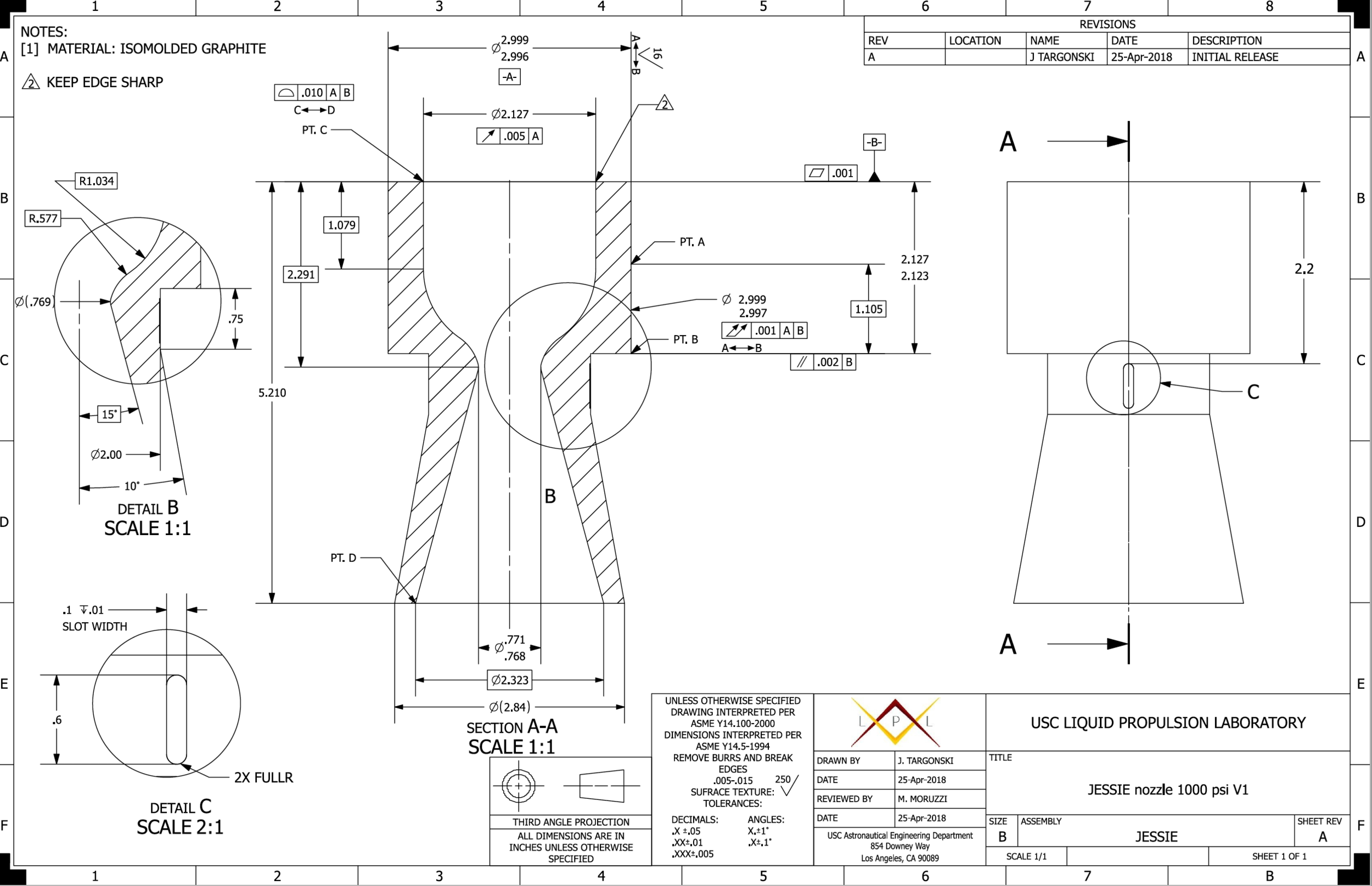
I was responsible for authoring all manufacturing drawings for post-print machining operations. At this current technological state of additive manufacturing, post-machining is still required to ensure proper assembly and functionality. All geometric dimensioning & tolerancing (GD&T) were per ASME Y14.5-1994, and featured callouts such as positional, flatness, profile of surface, parallel, and circular runout. Some critical features that required this callouts were sealing surfaces, O-ring grooves, sensor ports, & the throat area. In addition, a tolerance stack-up study was done to ensure a robust design for the various engine states. One example is the “axial stack-up” that can be seen on the left. This was to ensure the entire chamber wall was lined with an ablative thermal control, isomoled graphite.
Build
My role in during the build phase was to oversee the complete manufacturing process; 3D Print, Post-Process Operations, & Assembly. Being that this was the first time our lab utilized 3D printing to manufacture an engine, I had to develop a process flow of operations that may be required to ensure a successful print. Below is the post-print process workflow I established for our lab that illustrates all of the potential operations that may be required. Since each printed component has a different function, a study of which operations should be required needs to be done by an engineer on a per-part basis.
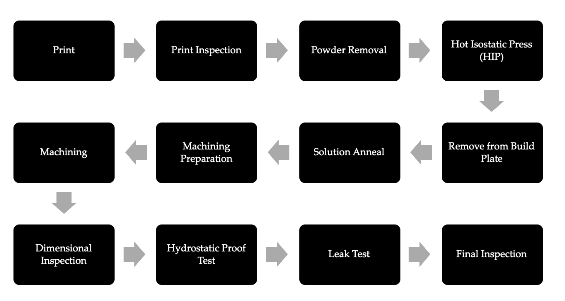
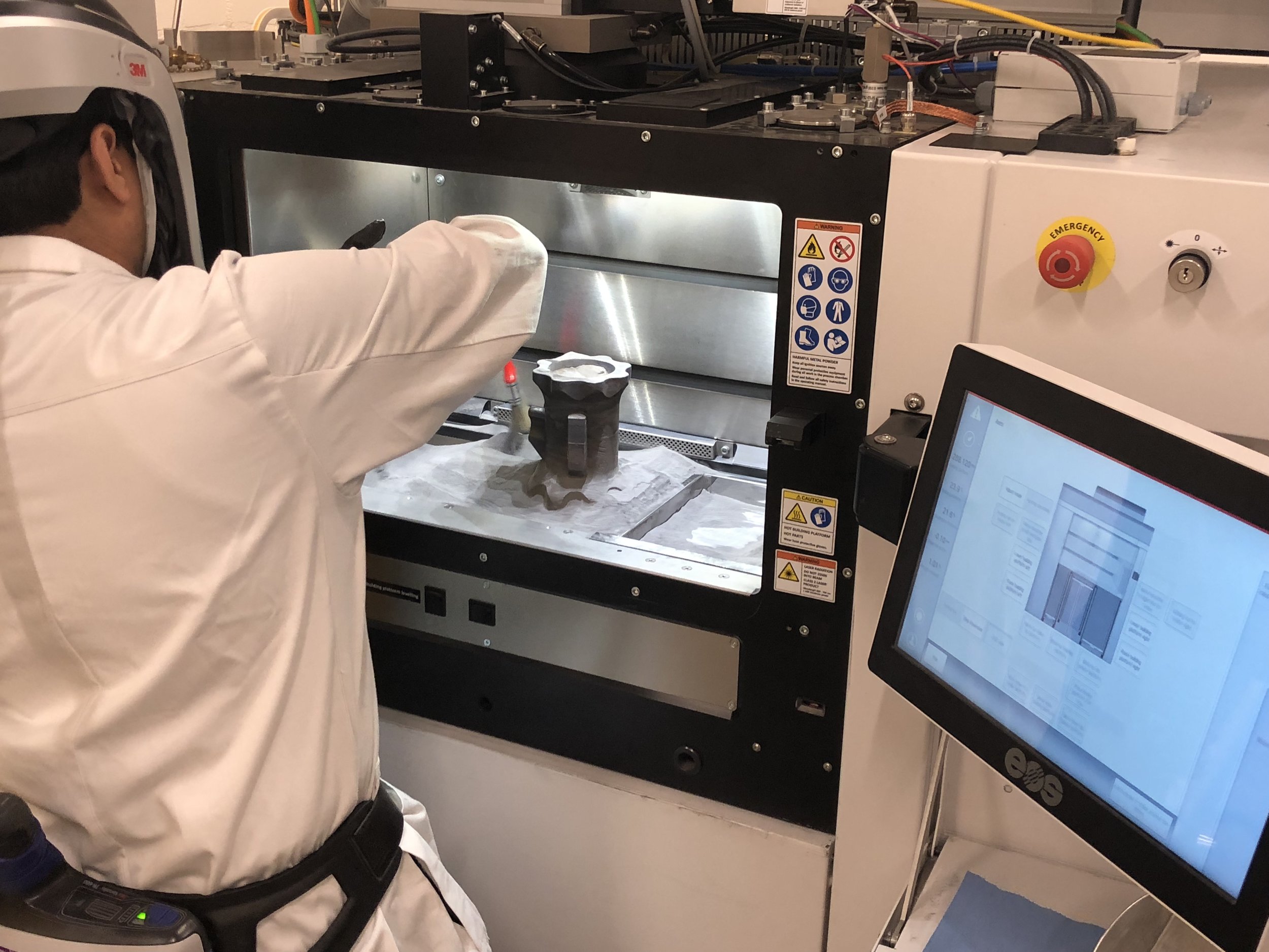
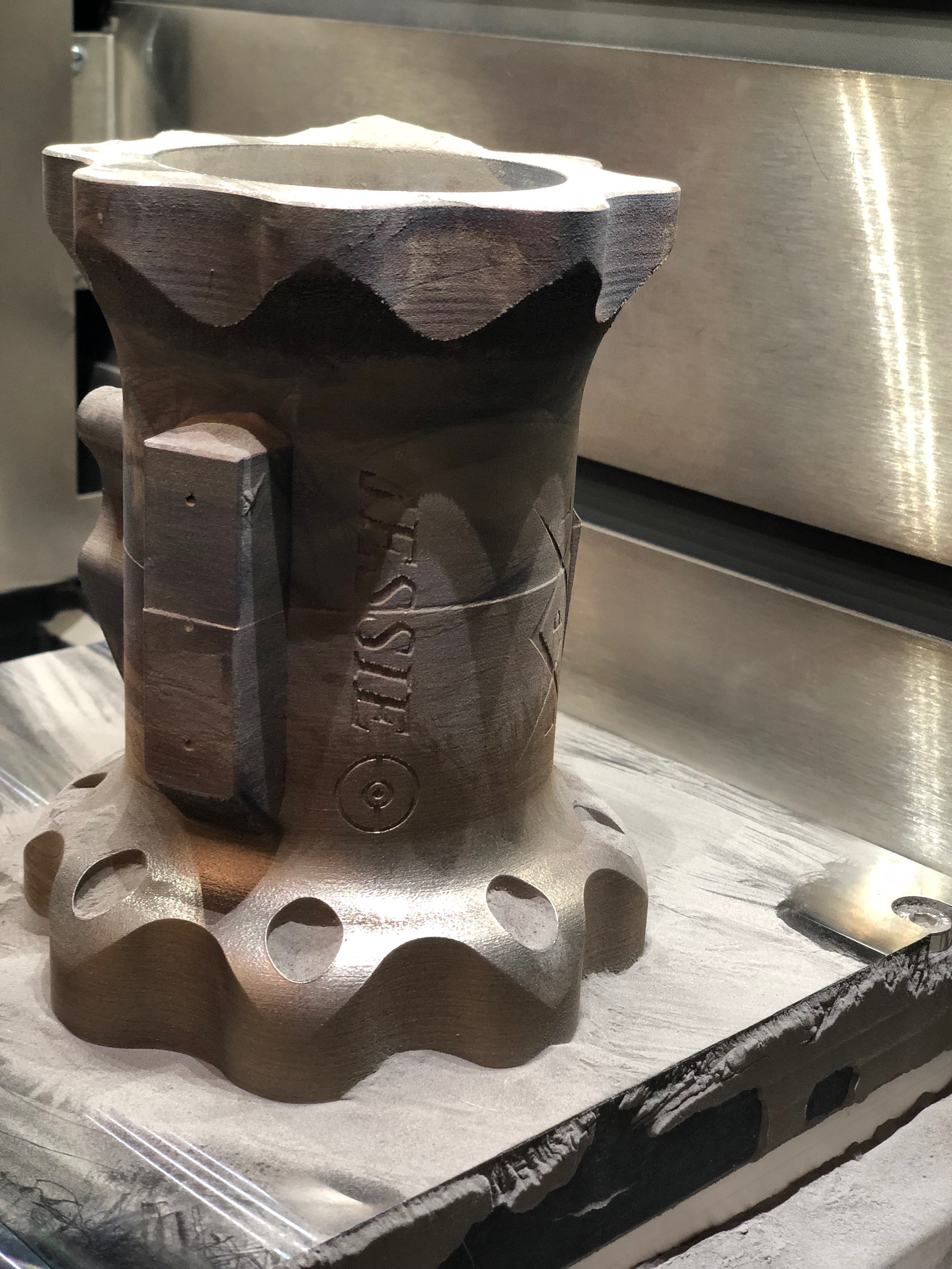
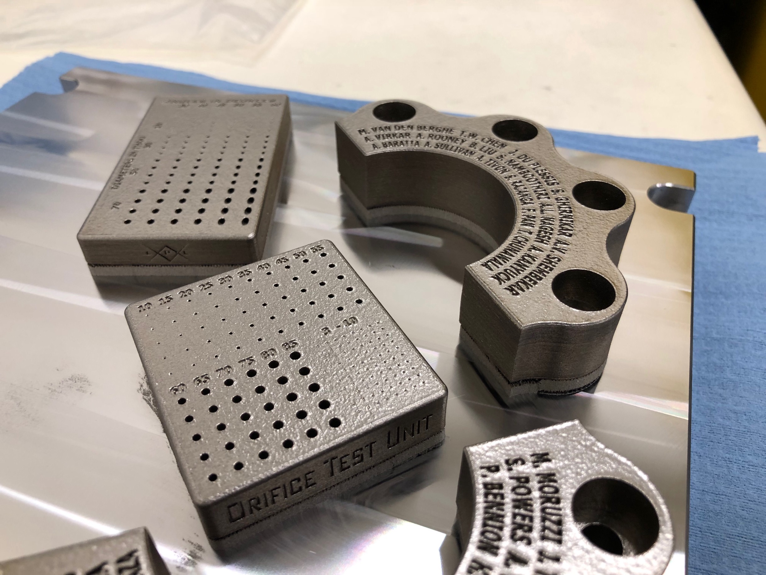
3D Print
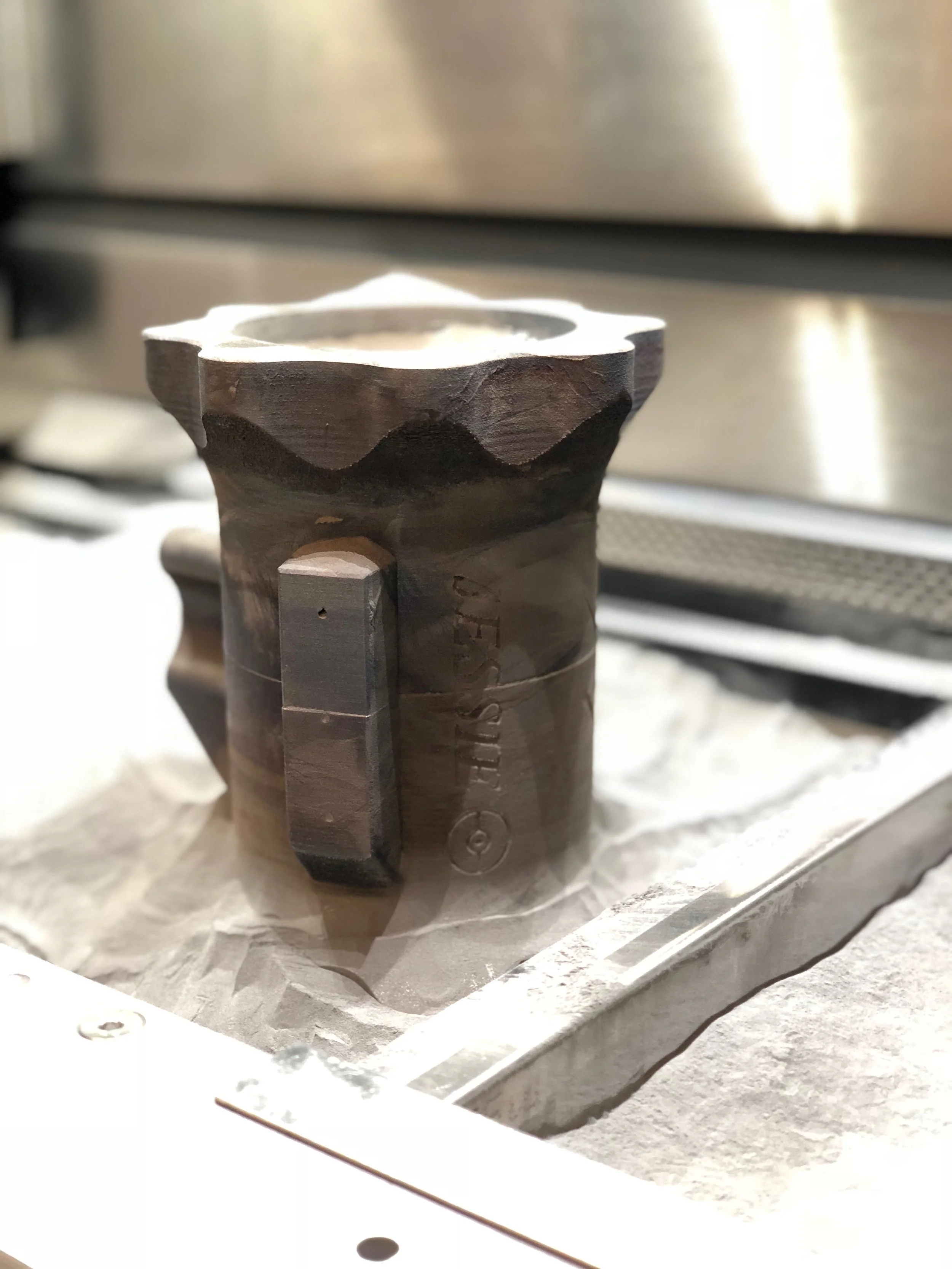
All major components besides that nozzle were fabricated via additive manufacturing. I worked alongside personal at the university’s Center of Advancement Manufacturing to get both the Jessie & James engines printed successfully. I coordinated print order, orientation, & grouping to increase the probability of a successful build which directly resulted in cheaper costs and faster lead times.
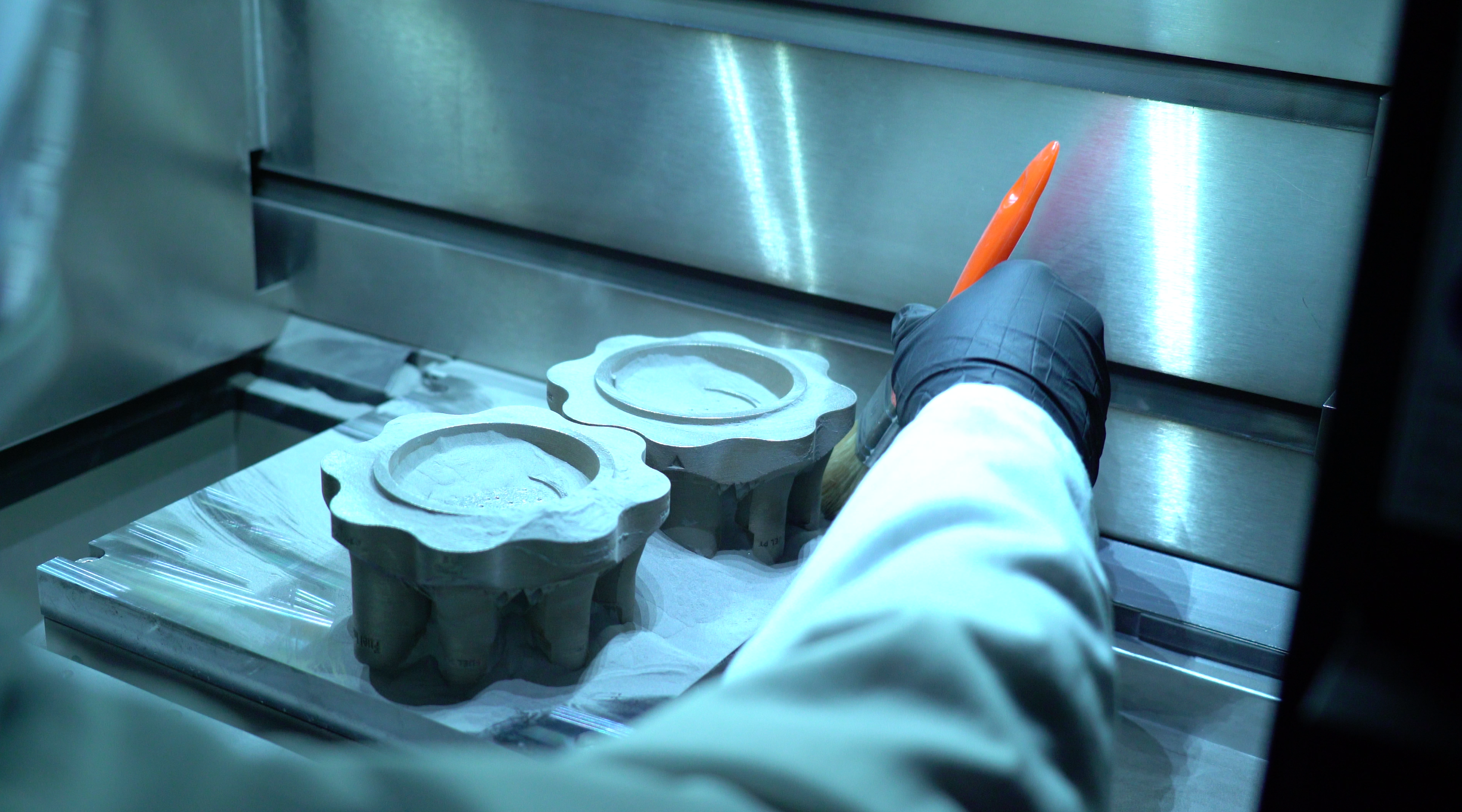
Post-Process Operations
The process workflow I introduced above was carefully considered for the Jessie & James engines. Because we planned to utilize an ablative liner for thermal control during operation, we did not need to increase the thermal properties that solution annealing provides. This allowed us to remove this step from the process flow and as a result made the machining operations easier with a quicker turnaround time.
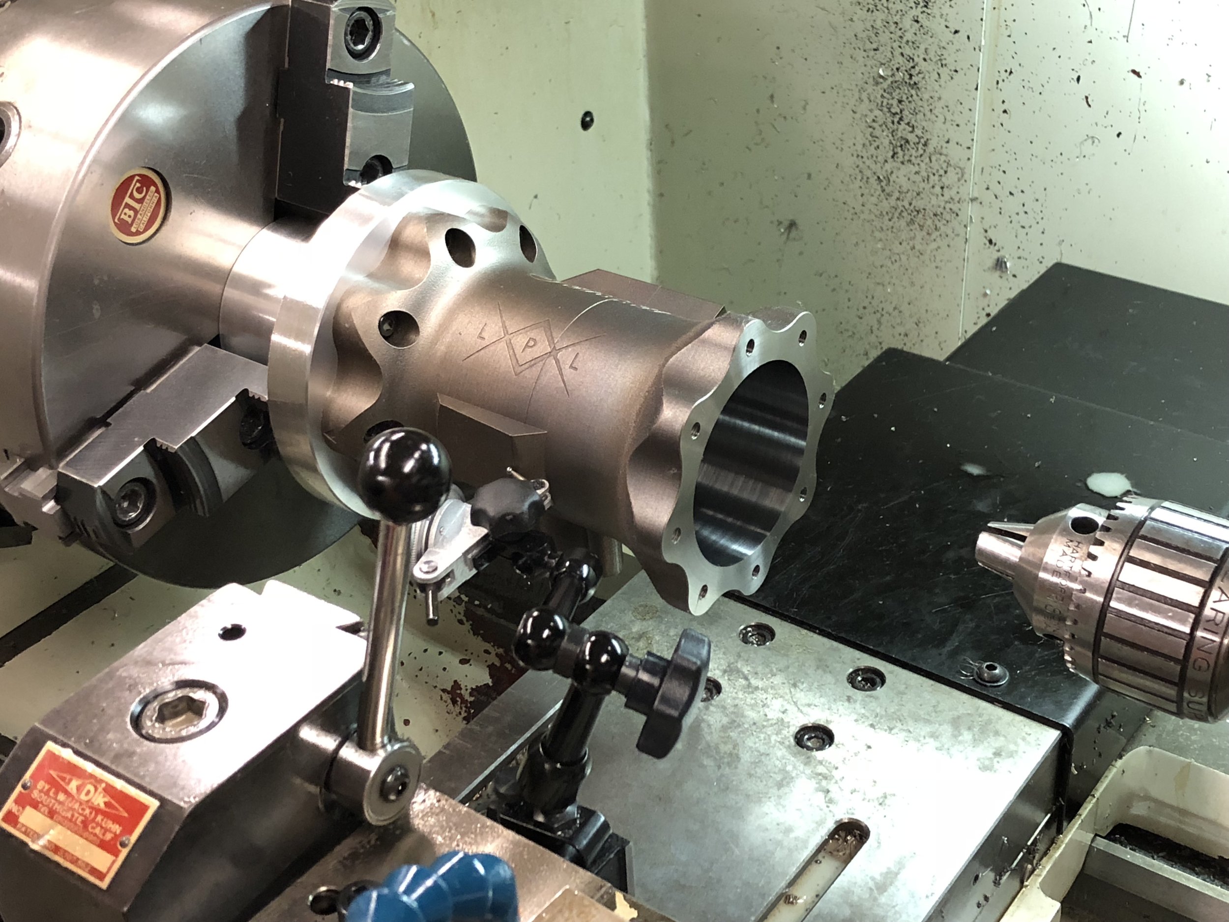
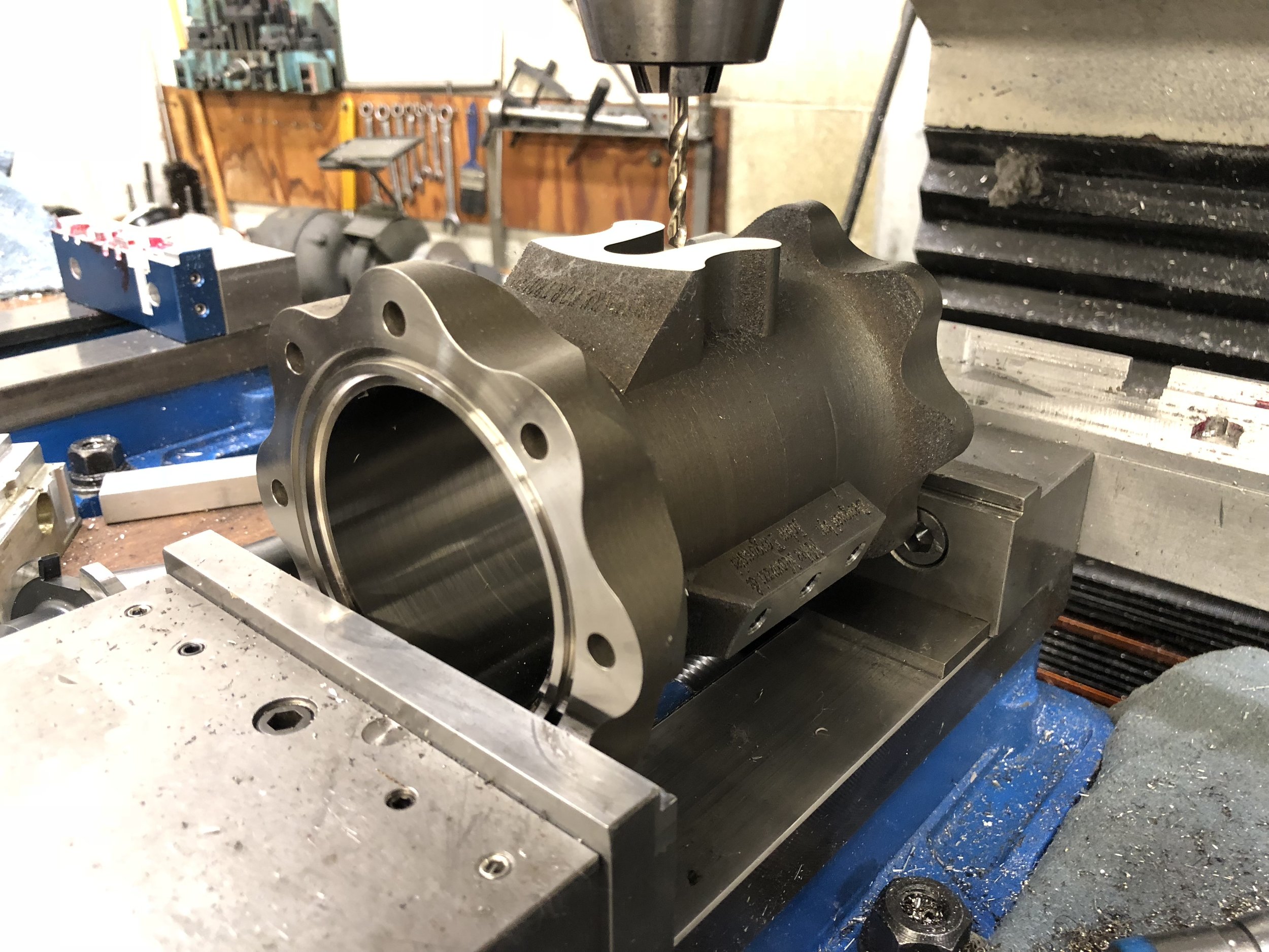
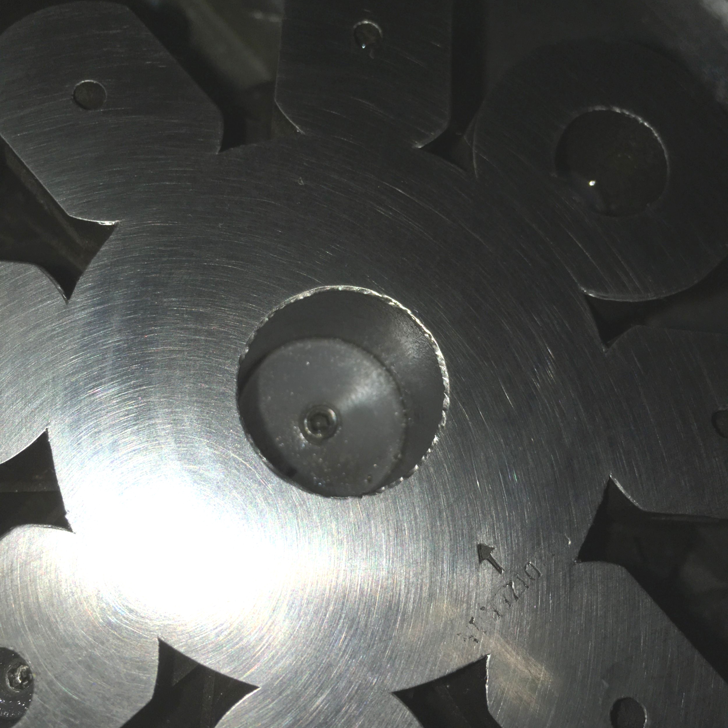
Machining & Dimensional Inspection

The machining and dimension inspection was done at the universities in-house machine shop. I oversaw all operations and coordinated with the machinists on a daily basis. Challenges during this process was limited equipment (no access to a 5-axis CNC), fixtures, and foreign object debris (FOD) prevention. The inspection of each component as well as the assembly as a whole was also down at the university’s machine shop.
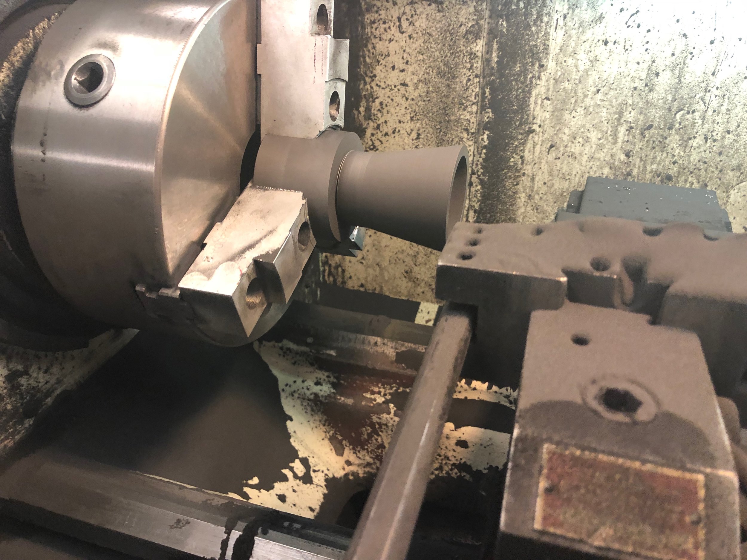
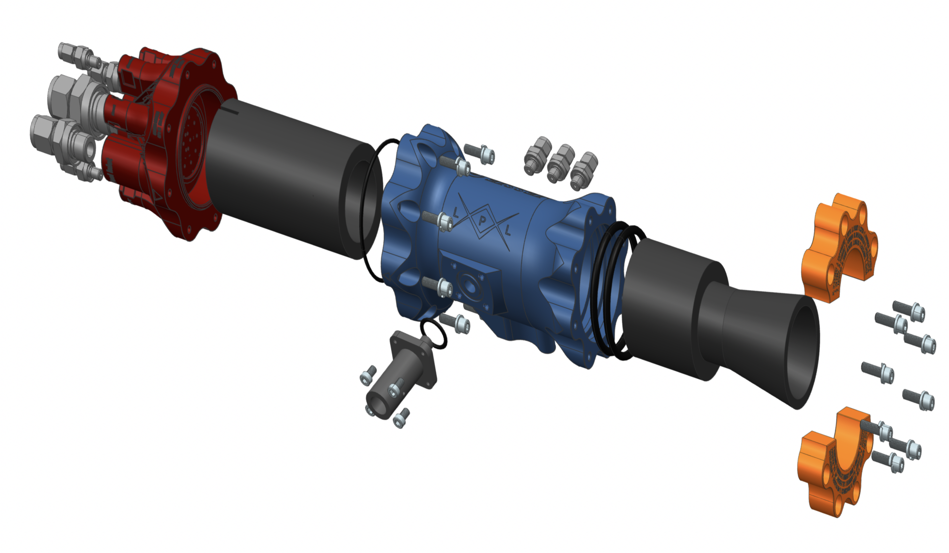
Assembly

My final role was leading and training members about the assembly of the entire engine. I was able to design the engine to be assembled in a trivial and simple manor. Some design implements to for ease of assembly was a reduced total number of parts, built in clocking and alignment features, one assembly direction, a minimized number & variation of fasteners, & printed in labels for sensor ports & propellant inlets. Once this was completed, I handed the engine off to the testing team that prepared the engine for static testing.
Today the J&J engines are both operational and serves as the laboratories workhorse engines!
I recently submitted two abstracts for publications that are under consideration to be presented at the 2019 IAC. They will discuss the design and manufacturing process of the Jessie & James rocket engines in detail & the development of the single-part 3D printed injector with as printed orifices.